One important resource a crane operator should be familiar with is a load chart. This will ensure crane safety and knowledge of each crane’s lifting capacity. There are many different types of cranes made by different companies and manufacturers. Knowing how to properly read and understand a load chart is imperative to the safety of the operator and the well-being of the cranes.
A few different types of rough terrain cranes such as a Grove, Link-Belt, Manitowoc, Kato, or Tadano will all have their own corresponding load charts. You will also come across unique load charts during the operation of a boom truck such as a Terex, National, Manitex, Pioneer, or Altec.
It’s important to never swap load charts or reference a load chart that does not belong to the specific type of crane you are using. This will help you as the operator stay safe and avoid costly repairs.
Load Chart Explanation
You will find the gross or rated capacities of a crane on this chart.
You can see that boom lengths of the crane are represented on the top row.The operating radius are represented by the numbers in the left column.
The boom’s angle and radius are measured with the boom loaded and weight. This is called the Loaded Boom Angle.
The intersection of the Boom Radius column and the corresponding Boom Length or the intersection of the Boom Angle Column and the Radius or Boom Length column will give you this crane’s “Gross Capacity”.
If the jib is stowed on the base of the boom you would deduct the “Stowed Jib Deductions” row for each corresponding boom length.
Gross Capacity Versus Net Capacity
It’s important when reading a crane’s load chart that you pay attention to the different types of capacities it can carry. There is the “Gross Capacity”, “Rated Capacity”, and “Net Capacity”.
The “Gross Capacity” and “Rated Capacity” are not the actual loads the hook can lift. Be sure when calculating the capacities that you always add the weight of the item being lifted. This includes any weight outside of the crane whether it is mounted, stowed on the boom, or hanging from the boom tip.
You will look to the “Net Capacity” for the maximum load the crane can carry. To avoid damage or structural failure the crane’s “Net Capacity” must never be exceeded.
The Gross Capacity must include the weight of anything and everything that is mounted or stowed on the boom of the crane or hanging from the boom tip. You will refer to the weight of these items as “Capacity Deductions”.
Capacity Deductions Include:
- The Main Load Block’s Weight
- Full Load Weight
- Jib Weight (Whether it is stowed, erected, or not being used.)
- The Headache Ball or Overhaul Ball’s Weight
- All Rigging Weight
- Hanging Cable Weight
Always refer to the load chart for what the manufacturer of your crane considers “Capacity Deductions”. These will vary from crane type to crane type.
GROSS CAPACITY – CAPACITY DEDUCTIONS = NET CAPACITY
The following are an example of capacity deductions in the cranes load chart. These items represent the amount of weight you would deduct from the gross capacity to determine the net capacity.
Jib Capacities
When lifting with either the 24 or 40ft jib you will refer to the “Gross Capacities” in the crane chart below. The “Gross Capacity” can be determined by selecting the jib and boom angle you will be using.
The “Boom Extension” may be referred to using different terms depending on which manufacturer’s load chart you are using. The “Pinned Boom” is considered a jib, fly, or boom extension. The names differ between each manufacturer’s chart whether you are looking at a Link Belt, Grove or Terex but they ultimately mean the same thing.
The chart on the left is common for Link Belt cranes where they use the term “fly”.
No matter what they are referred to as the primary purpose of a jib, fly, or boom extension is to increase the overall height a load may be lifted.
Dimensions
You will find the dimensions of the crane in the illustration below. Refer to this information when transporting the crane or setting it up in tight areas.
Line Pull
The “Line Pull” simply refers to the amount of rope a drum will hoist for a given layer.
The available line pull and maximum winch speed for the crane is represented in the image to the left.
Determining the of wire rope being used, then how many parts of line, will allow you to determine the available line pull.
The available line pull on the crane can be obtained by intersecting the two columns. The safe working load of the wire rope and the line pull of the hoist drum can be found in this chart. On some load charts you can find the available line pull for each layer of wire rope. This can be very helpful, but it is not included on all load charts by each manufacturer.
Notice how as the wraps on the drum increase, the line speed will increase while the available line pull decreases.
Area of Operation
Item Required by ANSI B30.5-1.1.3 Load Rating Chart and OSHA 1926.1433.
As a crane operator, you should always take the time to get familiar with the specific load chart of the crane you will be using prior to operating. Each manufacturer has their own load chart’s for each individual crane’s model and mounting configuration.
On the work area diagram (chart) you will be able to determine the crane’s operational quadrants. The diagram will clearly indicate the areas where no load is to be handled. This chart also specifies the different working areas of the crane per the manufacturer.
Examples of different working area diagrams are shown below:
Range Diagram
When trying to find the most appropriate configuration and positioning of your crane you should always refer to these diagrams. It will aid in determining the boom length needed to pick up and lift a load and setting up near structures. This will help avoid damage and aid in the safe operation of the crane.
When it comes to the wire rope, and deductions are required, you will want to refer to the working range diagram.
The working range diagram to the right is separated into:
- Load radius (vertical lines)
- Boom tip height (horizontal lines)
- Boom jib length (arched sections)
- Boom angles (angled lines)
- Caution area (prohibited area)
Load Chart Foot Notes
An important part of understanding a load chart is to read the foot notes. These are especially important to understand before operating the crane. Each crane will have specific foot notes that pertain to that individual crane type. To ensure safe crane operation read these notes carefully and following their instructions.
Outrigger / Crawler Extension
Crane load charts differ by crane type. This is why it is important to read and understand each one individually. In this case of the crane below you can see that this has many lifting options where other cranes only have capacities listed for outriggers fully extended and set.
On this crane type you have the option of lifting:
- On tires
- Outriggers fully retracted
- Outriggers fully extended
- Outriggers intermediate extended
This is especially helpful when operating in small spaces. It will allow you different options that you may not have with other cranes. However, due to the options, the crane is considered less stable.
The wider you can set your crane’s stance the further its tipping axis will be. This creates a more stable crane. Luckily, some crawler cranes have the ability to extend their tracks and widen their stance to improve the stability of the crane when working over the sides.

Counterweights
Depending on the crawler crane’s load charts you may find different capactiies for crawlers retracted and crawlers extended. Like outriggers the farther the tipping axis the more stability.
On some cranes you might find a counterweight. However, you will not find this on all cranes. Specifically, boom trucks do not come equipped with a counterweight.
On Link Belt mobile cranes you may find that their load charts show a variable counterweight configuration. This allows the travel with lighter loads on public roads or bridges where weight is a factor.
In order to gain more capacity on your crane you need more counterweight. To stay safe avoid operating a crane over the side without outriggers properly extended. This will help avoid the loss of backward stability.
Stability (Tipping) vs. Structural Strength
Tipping Capacity / Stability
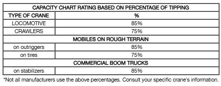
The tipping capacity is based on the weight necessary to tip the crane over. It’s important to read the load chart specific to the crane type you are using to determine the tipping capacity. The tipping capacity is considered the stability of the crane and can be found below the bold line. Each unique load chart has a way to distinguish between the two.
Structural Strength
This limit is based on actual strength of material, boom, jib, etc.
You can find the structural capacities in a load chart by checking the shaded area, above a bold line, in bold type or marked with an asterisk *
Factors that Reduce Load Capacities Production Operations
3 operations that may cause full load chart ratings to not apply would be:
- Pouring Concrete
- Steel Erection
- Dragline, magnet, and clamshell work, etc.
UNLEVEL CRANE:
All load charts are based on firm level ground. Below is an example of possible capacity loss due to a crane being unlevel.
SIDE LOADING:
This is strictly forbidden by the manufacturer. Crane booms are designed for maximum strength downward not to the side. This can cause the crane to tip.
SWING RATE:
It’s important not to rush the swing. Starting and stopping the swing too rapidly and will cause a side loading condition and runs the risk of tipping.
INCREASE IN LOAD RADIUS:
An increase in load radius happens when a load is applied. The boom deflection can cause the load to drift away from the crane.

